Hydraulics
Knowledge Hub
Hydraulics
Knowledge Hub
We’re more than just a provider—we’re your your trusted resource for all things fluid power. From calculators and tools to expert articles and videos, we provide the knowledge you need to tackle any job with confidence.
We’re more than just a provider—we’re your your trusted resource for all things fluid power. From calculators and tools to expert articles and videos, we provide the knowledge you need to tackle any job with confidence.


Expert Guidance, Dedicated Support
Keeping your operations running at peak performance is our priority. Our expert support team is ready to assist you pre- and post-sale. With Lunchbox training programs and technical guidance, we provide the knowledge and resources you need to make the most of your hydraulic equipment.
Our Latest Educational Articles
For over 40 years, Bailey has been a trusted leader in the manufacturing and distribution of hydraulic and electronic solutions. Dive into our educational content to expand your knowledge and discover how our expertise can support your success.
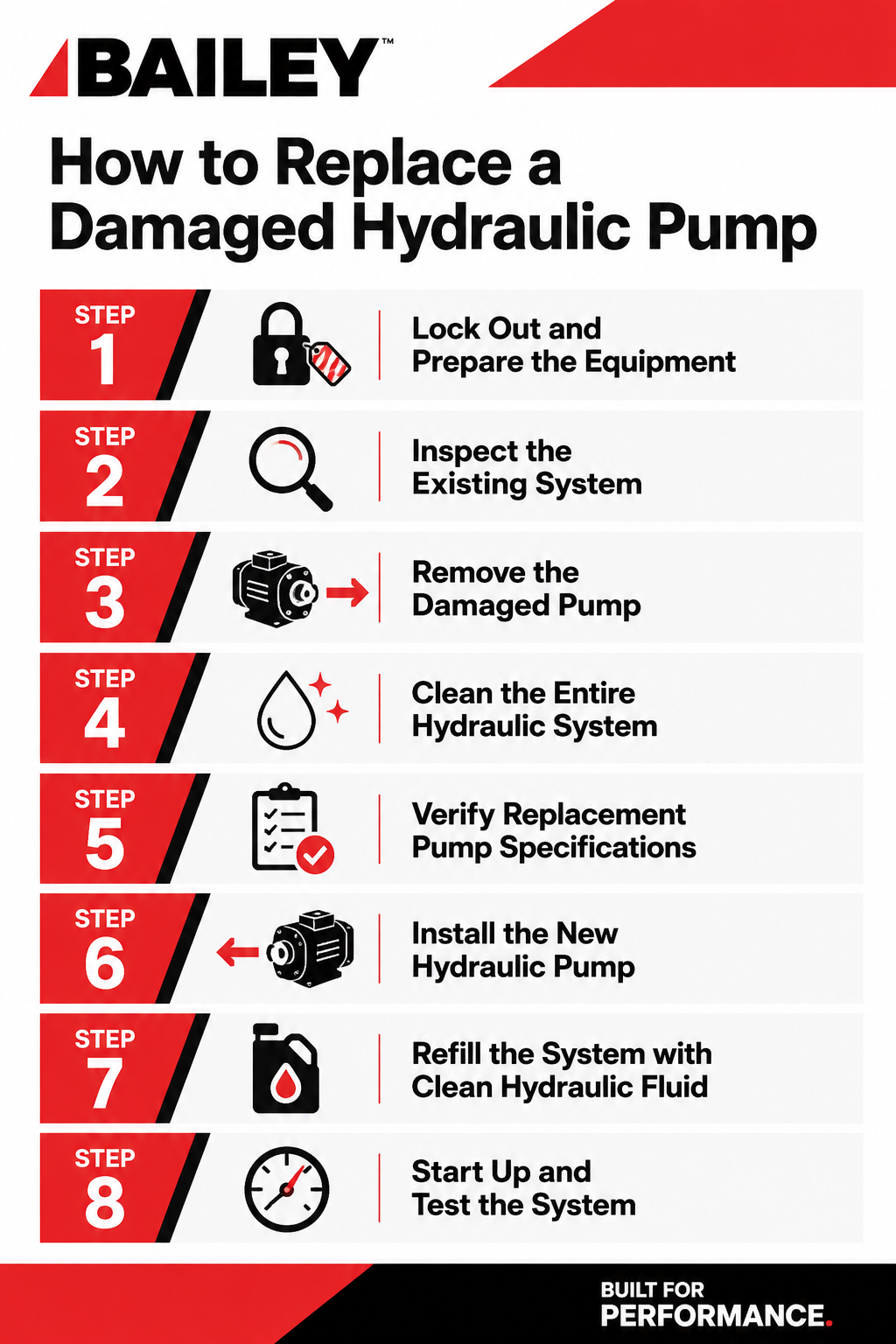
When a pump begins to fail, performance issues can quickly spread throughout your equipment, including overheating, slow operation, loss of pressure, unusual noise, or complete system shutdown.
Replacing a damaged hydraulic pump requires careful inspection, system cleaning, proper installation, and post-installation testing to prevent repeat failures and unnecessary downtime.
This guide will walk you through the essential steps for replacing a hydraulic pump safely and correctly.
Signs Your Hydraulic Pump Needs Replacement
Before replacing a pump, it’s important to confirm the pump is actually the source of the issue. Common symptoms of pump failure include:
- Excessive noise or whining
- Slow or erratic actuator movement
- Reduced hydraulic pressure
- Fluid overheating
- Visible leaks around the pump housing
- Metal contamination in hydraulic fluid
- Cavitation or vibration
- Loss of efficiency under load
In many cases, contamination, overheating, or improper fluid levels can actually contribute to pump failure. Identifying the root cause before installing a new pump helps prevent repeated damage.
Step 1: Lock Out and Prepare the Equipment
Safety should always come first.
Before beginning any hydraulic pump replacement:
- Shut down the machine completely
- Relieve hydraulic system pressure
- Disconnect power sources
- Follow all lockout/tagout procedures
- Allow components and fluid to cool
Hydraulic systems can retain pressure even after shutdown, so never loosen fittings until pressure has been fully relieved.
Step 2: Inspect the Existing System
A failed pump is often the result of another issue within the hydraulic system. Before removing the old pump, inspect:
- Hydraulic fluid condition
- Reservoir cleanliness
- Suction lines and fittings
- Filters and strainers
- Relief valve settings
- Couplings and shafts
- Hose condition
Contaminated fluid is one of the leading causes of hydraulic pump damage. Dirt, metal particles, moisture, and degraded oil can quickly destroy a replacement pump if the system is not cleaned thoroughly.
Step 3: Remove the Damaged Pump
Once the system has been inspected:
- Drain hydraulic fluid if necessary
- Label and disconnect hydraulic lines
- Remove mounting hardware
- Disconnect the drive coupling or PTO
- Carefully remove the damaged pump
During removal, inspect the old pump for signs of:
- Scoring
- Excessive wear
- Burnt fluid residue
- Shaft damage
- Seal failure
These clues can help identify what caused the failure.
Step 4: Clean the Entire Hydraulic System
This step is critical.
Installing a new hydraulic pump into a contaminated system can lead to immediate damage and shortened pump life. Best practices include:
- Flushing hydraulic lines
- Cleaning the reservoir
- Replacing filters
- Inspecting suction strainers
- Removing debris from hoses and fittings
We strongly recommend fully cleaning the system before installing a replacement pump.
Step 5: Verify Replacement Pump Specifications
Not all hydraulic pumps are interchangeable.
Before installation, confirm the replacement pump matches the original system requirements, including:
- Flow rate (GPM)
- Pressure rating
- Rotation direction
- Mounting style
- Shaft configuration
- Port sizes
- Displacement
Using an incorrectly sized pump can create performance issues, excessive heat, or even premature failure.
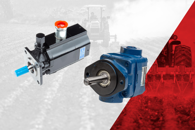
At Bailey International, we offer a wide range of hydraulic pump solutions, including gear pumps, piston pumps, vane pumps, hand pumps, and two-stage pumps designed for mobile hydraulic applications.
Step 6: Install the New Hydraulic Pump
When installing the replacement pump:
- Pre-fill the pump with clean hydraulic fluid if recommended
- Align shafts and couplings properly
- Secure mounting hardware evenly
- Reconnect hydraulic lines carefully
- Ensure all fittings are properly tightened
Improper alignment can place excess stress on bearings and seals, reducing pump life.
It’s also important to ensure the pump has an unobstructed oil supply during startup to prevent dry running or cavitation.
Step 7: Refill the System with Clean Hydraulic Fluid
Always use clean hydraulic oil with the correct viscosity recommended for the application.
After refilling:
- Bleed air from the system
- Check fluid levels
- Inspect for leaks
- Replace filters if needed
Air trapped in hydraulic systems can cause erratic performance and cavitation.
Step 8: Start Up and Test the System
Initial startup should be performed gradually.
Recommended startup procedure:
- Run the system at low RPM first
- Monitor pressure gauges
- Watch for leaks or unusual noises
- Cycle cylinders and motors slowly
- Recheck fluid levels
Pressure settings should always remain within the limits of the lowest-rated component in the hydraulic system.
Common Mistakes to Avoid
When replacing a hydraulic pump, avoid these common errors:
- Reusing contaminated hydraulic fluid
- Failing to replace filters
- Installing the wrong pump size
- Ignoring suction line restrictions
- Running the pump dry at startup
- Overlooking relief valve settings
- Skipping system flushing
Many repeat pump failures are caused by unresolved system contamination or installation issues.
Preventing Future Hydraulic Pump Failures
Preventive maintenance plays a major role in extending hydraulic pump life. Key maintenance practices include:
- Monitoring fluid cleanliness
- Replacing filters regularly
- Checking fluid levels
- Inspecting hoses and fittings
- Monitoring operating temperatures
- Addressing leaks immediately
Routine inspections help identify issues before they become costly failures.
Replacing a damaged hydraulic pump is really an opportunity to improve the reliability, efficiency, and longevity of your entire hydraulic system. By identifying the root cause of failure, thoroughly cleaning the system, and installing the correct replacement pump, operators can reduce downtime and avoid repeat failures.
At Bailey, we understand that every minute of downtime impacts productivity. That’s why we offer a comprehensive selection of hydraulic pumps, motors, cylinders, valves, reservoirs, and power units backed by knowledgeable hydraulic experts who can help you find the right solution for your application.
Whether you’re replacing a failed pump, upgrading your hydraulic system, or sourcing hard-to-find components, Bailey International is ready to help.
Explore our full line of hydraulic pumps or contact our team today to get expert support for your next hydraulic repair or replacement project.
How to Replace a Damaged Hydraulic Pump
At Bailey, we want to keep you moving forward, always. So, we’ve decided to highlight the most common hydraulic failures, and more importantly, how to prevent them through smart maintenance and component selection.
.png)
1. Fluid Contamination
The Problem:
Contaminants like dirt, metal particles, and water are the leading causes of hydraulic system failures. They accelerate wear, clog components, and reduce efficiency.
Prevention:
Implement strict filtration practices. Use high-quality filters and replace them on schedule. Store fluid properly, use clean transfer equipment, and regularly test fluid cleanliness. Sealed reservoirs and desiccant breathers can further reduce contamination risk.
2. Overheating
The Problem:
Excessive heat degrades hydraulic fluid, damages seals, and reduces system efficiency.
Prevention:
Maintain proper fluid levels and ensure cooling systems (heat exchangers, fans) are functioning correctly. Use the right viscosity fluid for your operating environment, and monitor system temperature regularly to catch issues early.
3. Improper Fluid Selection
The Problem:
Using the wrong hydraulic fluid can lead to poor lubrication, increased wear, and system inefficiency.
Prevention:
Always follow manufacturer recommendations for fluid type and viscosity. Consider operating temperature ranges and load conditions when selecting fluid. Periodic fluid analysis helps confirm performance and identify degradation.
4. Air Entrapment and Aeration
The Problem:
Air in the system causes erratic operation, noise, and increased oxidation of fluid.
Prevention:
Check for loose fittings, cracked hoses, and low fluid levels. Ensure proper reservoir design and return line placement to minimize turbulence. Bleed the system after maintenance to remove trapped air.
5. Seal Failure
The Problem:
Worn or damaged seals lead to leaks, contamination, and loss of pressure.
Prevention:
Inspect seals regularly for wear, hardening, or cracking. Use seals compatible with your hydraulic fluid and operating conditions. Avoid excessive heat and pressure spikes that can shorten seal life.
6. Hose and Fitting Failures
The Problem:
Hoses can crack, burst, or loosen over time, leading to leaks or sudden system failure.
Prevention:
Perform routine visual inspections for abrasion, bulging, or leaks. Make sure hoses are properly routed and secured to prevent rubbing or kinking. Replace hoses based on service life, not just visible damage.
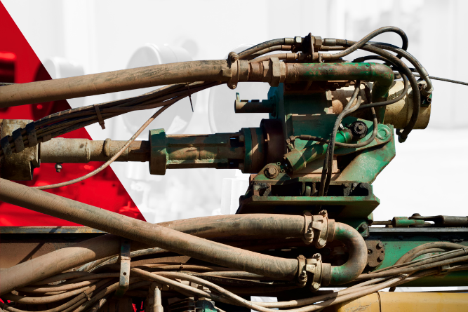
7. Pump Failure
The Problem:
Hydraulic pumps can fail due to cavitation, contamination, or excessive wear.
Prevention:
Maintain proper inlet conditions to prevent cavitation. Check for adequate fluid supply and avoid restrictions. Keep fluid clean and monitor for unusual noise or vibration. Regularly check alignment and operating pressures.
8. Cylinder Drift or Leakage
The Problem:
Internal leakage in cylinders can cause drift, reducing precision and efficiency.
Prevention:
Check cylinder seals and rods for wear or scoring. Maintain clean fluid to prevent internal damage. Rebuild or replace cylinders showing signs of internal bypassing before failure worsens.
9. Valve Malfunction
The Problem:
Sticking or worn valves can disrupt flow control, leading to erratic system behavior.
Prevention:
Keep fluid clean and free of varnish buildup. Exercise valves periodically to prevent sticking. Inspect for wear and replace components as needed to maintain precise control.
Hydraulic failures don’t have to be inevitable. With the right components, proper system design, and a proactive maintenance strategy, you can significantly extend equipment life and reduce downtime.
At Bailey, we’re committed to delivering hydraulic solutions that keep your equipment and your business moving forward. Reach out to us today for a free consultation.
Moving Machinery Forward: How to Prevent the Most Common Hydraulic Failures
Longevity isn’t just a benefit in heavy machinery; it’s a necessity. At Bailey International, designing for longevity is embedded in everything we do.
Hydraulic systems' ability to deliver consistent power and controlled motion makes them ideal for demanding environments where durability is critical. Longevity in hydraulics starts with robust design of components that can withstand high pressures, heavy loads, and continuous operation without compromising performance.
At Bailey, longevity is engineered into every hydraulic solution. Whether it’s cylinders designed for up to 5,000 PSI or custom configurations for unique applications, each component is built with high-performance materials and precise specifications. From chrome-plated rods to integrated to intricate valve systems, these design choices reduce wear, improve efficiency, and extend operational life.
In fact, customization plays an essential role in longevity. Off-the-shelf solutions may work temporarily, but systems designed specifically for the environment they operate in deliver sustained performance. Our collaborative engineering approach ensures that hydraulic systems are not just functional, but optimized for long-term durability and reduced downtime.
Electronics Designed for Precision and Reliability
As machinery evolves, electronics are becoming as integral as hydraulics in achieving longevity. Electronic controls, such as joysticks, sensors, and control systems, enable operators to manage complex machinery with precision and consistency. This precision reduces operator error, minimizes mechanical strain, and ultimately extends the life of the entire system.
From rugged joystick controls to fully integrated electro-hydraulic solutions, each component is built to withstand real-world conditions while delivering intuitive, responsive control. By integrating electronics directly into system design, machines operate more efficiently, reducing unnecessary stress on hydraulic components and improving overall life-cycle performance.
Customization is once again the differentiator. Through Bailey’s Build Custom Program, electronic controls are tailored to the exact needs of the application, ensuring seamless integration with hydraulic systems and operator workflows. The result is smarter machinery that not only performs better today but continues to deliver value over time, adapting to evolving operational demands.

Building for What’s Next
Designing for longevity means thinking beyond immediate performance; it’s about creating solutions that stand the test of time. At Bailey, that commitment is reflected in our engineering expertise, custom solutions, and dedication to supporting our customers at every stage of their equipment life-cycle. From hydraulics that deliver consistent power to electronics that enhance precision and control, every solution is built to move your machinery forward.
Ready to design equipment that lasts? Partner with Bailey today to build custom hydraulic and electronic solutions engineered for longevity.
.png)
Moving Machinery Forward: Designing for Longevity

Build Custom with Bailey
Custom hydraulic and electronic solutions tailored to your unique needs. With expert engineering support and a comprehensive range of components, we streamline your project from design to delivery for seamless performance.